stdClass Object
(
[nazev] => Laboratory of Inorganic Materials
[adresa_url] =>
[api_hash] =>
[seo_desc] =>
[jazyk] =>
[jednojazycny] =>
[barva] => cervena
[indexace] => 1
[obrazek] =>
[ga_force] =>
[cookie_force] =>
[secureredirect] =>
[google_verification] =>
[ga_account] =>
[ga_domain] =>
[ga4_account] => G-VKDBFLKL51
[gtm_id] =>
[gt_code] =>
[kontrola_pred] =>
[omezeni] => 0
[pozadi1] => 6_0868.jpg
[pozadi2] =>
[pozadi3] =>
[pozadi4] =>
[pozadi5] =>
[robots] =>
[htmlheaders] =>
[newurl_domain] => 'lam.vscht.cz'
[newurl_jazyk] => 'en'
[newurl_akce] => '[en]'
[newurl_iduzel] =>
[newurl_path] => 8548/20508/20510
[newurl_path_link] => Odkaz na newurlCMS
[iduzel] => 20510
[platne_od] => 31.10.2023 17:03:00
[zmeneno_cas] => 31.10.2023 17:03:56.393301
[zmeneno_uzivatel_jmeno] => Jan Kříž
[canonical_url] =>
[idvazba] => 25426
[cms_time] => 1714117061
[skupina_www] => Array
(
)
[slovnik] => stdClass Object
(
[logo_href] => /
[logo] =>  [logo_mobile_href] => /
[logo_mobile] =>
[google_search] => 001523547858480163194:u-cbn29rzve
[social_fb_odkaz] =>
[social_tw_odkaz] =>
[social_yt_odkaz] =>
[intranet_odkaz] => http://intranet.vscht.cz/
[intranet_text] => Intranet
[mobile_over_nadpis_menu] => Menu
[mobile_over_nadpis_search] => Search
[mobile_over_nadpis_jazyky] => Languages
[mobile_over_nadpis_login] => Login
[menu_home] => Homepage
[drobecky] => You are here: VŠCHT Praha – FCHT – Laboratory of Inorganic Materials
[aktualizovano] => Updated
[autor] => Author
[paticka_budova_a_nadpis] => BUILDING A
[paticka_budova_a_popis] => Rector,
Department of Communications,
Department of Education,
FCT Dean’s Office,
Centre for Information Services
[paticka_budova_b_nadpis] => BUILDING B
[paticka_budova_b_popis] => Department of R&D, Dean’s Offices:
FET,
FFBT,
FCE,
Computer Centre,
Department of International Relations,
Bursar
[paticka_budova_c_nadpis] => BUILDING C
[paticka_budova_c_popis] => Crèche Zkumavka,
General Practitioner,
Department of Economics and Management,
Department of Mathematics
[paticka_budova_1_nadpis] => NATIONAL LIBRARY OF TECHNOLOGY
[paticka_budova_1_popis] =>
[paticka_budova_2_nadpis] => CAFÉ CARBON
[paticka_budova_2_popis] =>
[paticka_adresa] => Laboratory of Inorganic Materials
Joint Workplace of The UCT Prague and The Institute of Rock Structure and Mechanics, v.v.i.
[logo_mobile_href] => /
[logo_mobile] =>
[google_search] => 001523547858480163194:u-cbn29rzve
[social_fb_odkaz] =>
[social_tw_odkaz] =>
[social_yt_odkaz] =>
[intranet_odkaz] => http://intranet.vscht.cz/
[intranet_text] => Intranet
[mobile_over_nadpis_menu] => Menu
[mobile_over_nadpis_search] => Search
[mobile_over_nadpis_jazyky] => Languages
[mobile_over_nadpis_login] => Login
[menu_home] => Homepage
[drobecky] => You are here: VŠCHT Praha – FCHT – Laboratory of Inorganic Materials
[aktualizovano] => Updated
[autor] => Author
[paticka_budova_a_nadpis] => BUILDING A
[paticka_budova_a_popis] => Rector,
Department of Communications,
Department of Education,
FCT Dean’s Office,
Centre for Information Services
[paticka_budova_b_nadpis] => BUILDING B
[paticka_budova_b_popis] => Department of R&D, Dean’s Offices:
FET,
FFBT,
FCE,
Computer Centre,
Department of International Relations,
Bursar
[paticka_budova_c_nadpis] => BUILDING C
[paticka_budova_c_popis] => Crèche Zkumavka,
General Practitioner,
Department of Economics and Management,
Department of Mathematics
[paticka_budova_1_nadpis] => NATIONAL LIBRARY OF TECHNOLOGY
[paticka_budova_1_popis] =>
[paticka_budova_2_nadpis] => CAFÉ CARBON
[paticka_budova_2_popis] =>
[paticka_adresa] => Laboratory of Inorganic Materials
Joint Workplace of The UCT Prague and The Institute of Rock Structure and Mechanics, v.v.i.
Technická 5
166 28 Prague 6 – Dejvice
IČO: 60461373 / VAT: CZ60461373
Czech Post certified digital mail code: sp4j9ch
Copyright: UCT Prague 2015
Technical support by the Computing Centre.
[paticka_odkaz_mail] => mailto:Vladislava.Tonarova@vscht.cz
[zobraz_desktop_verzi] => switch to desktop version
[social_fb_title] =>
[social_tw_title] =>
[social_yt_title] =>
[zobraz_mobilni_verzi] => switch to mobile version
[paticka_mapa_odkaz] =>
[nepodporovany_prohlizec] => For full access, please use different browser.
[preloader] => Wait a second...
[social_in_odkaz] =>
[social_li_odkaz] =>
)
[poduzel] => stdClass Object
(
[20558] => stdClass Object
(
[obsah] =>
[poduzel] => stdClass Object
(
[20560] => stdClass Object
(
[obsah] =>
[iduzel] => 20560
[canonical_url] => //lam.vscht.cz
[skupina_www] => Array
(
)
[url] =>
[sablona] => stdClass Object
(
[class] =>
[html] =>
[css] =>
[js] =>
[autonomni] =>
)
)
[20561] => stdClass Object
(
[obsah] =>
[iduzel] => 20561
[canonical_url] => //lam.vscht.cz
[skupina_www] => Array
(
)
[url] =>
[sablona] => stdClass Object
(
[class] =>
[html] =>
[css] =>
[js] =>
[autonomni] =>
)
)
[20562] => stdClass Object
(
[obsah] =>
[iduzel] => 20562
[canonical_url] => //lam.vscht.cz
[skupina_www] => Array
(
)
[url] =>
[sablona] => stdClass Object
(
[class] =>
[html] =>
[css] =>
[js] =>
[autonomni] =>
)
)
)
[iduzel] => 20558
[canonical_url] =>
[skupina_www] => Array
(
)
[url] =>
[sablona] => stdClass Object
(
[class] =>
[html] =>
[css] =>
[js] =>
[autonomni] =>
)
)
[20559] => stdClass Object
(
[obsah] =>
[poduzel] => stdClass Object
(
[20563] => stdClass Object
(
[nazev] =>
[seo_title] => Laboratory of Inorganic Materials
[seo_desc] =>
[autor] =>
[autor_email] =>
[obsah] =>
|
Laboratory of Inorganic Materials is joint working place of the University of Chemistry and Technology Prague and the Institute of rock structure and mechanics ASCR, v.v.i. Laboratory activity evenly covers the area of education and both basic and applied research.
|
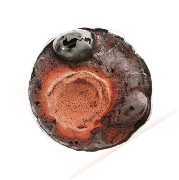
Melting space for the vitrification of radioactive materials |

|
|
For students
|
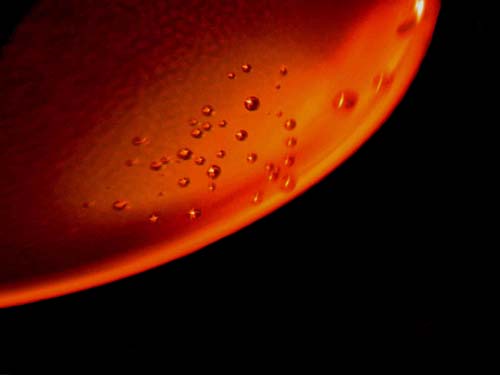
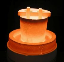
| Bubble in glass containig Na2SO4 condensate |
|
Laboratory members are involved in the education within bachelor and master study programs Chemistry and Materials. Doctoral students of the study program Chemistry and Technology of Inorganic Materials work closely with us when assisting solved research projects, completing required coursework and writing and defending a dissertation about their research project. |
|
 |
|
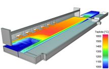
| The result of the mathematical model of the flow in the melting chamber - sectional view showing the formation of spiral flow, which allows to increase the efficiency of the melting process. |
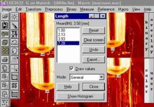
Image analysis - measurement of the size of a bubble in the melt. |

Laboratory of Inorganic Materials was created from the original Laboratory for chemistry and technology of silicates and ICT Prague and ASCR founded in 1961. In 2012, the Laboratory was transformed into a Joint workplace of the University of Chemistry and Technology Prague UCT Prague) and the Institute of Rock Structure and Mechanics ASCR, v.v.i. The Laboratory cooperates with materials-oriented UCT Prague departments, especially the Department of glass and ceramics. In addition to the labs in UCT Prague (Building A, Room A04), we also work at the Institute of Rock Structure and Mechanics ASCR v.v.i., V Holešovičkách 41, 180 00 Prague 8.
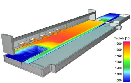
Temperature distribution on the top melt level in a glass melting space
Postgraduate study programme: Chemistry and Technology of Materials
Field of study: Chemistry and technology of inorganic materials
Themes of the postgraduate studies
Supervisor: Prof. Ing. Lubomír Němec, DrSc.
|
Supervisor: Doc. Ing. Jaroslav Kloužek, CSc.
|
Supervisor: Doc. Ing. Jaroslav Kloužek, CSc. |
Supervisor: Prof. Ing. Lubomír Němec, DrSc.
|
Research areas |
Glass melting processes and their modelling |
New glass melting concepts |
|||
|
|
Mathematical modeling is traditional tool for the analysis of glass melting process. CFD methods calculate velocity and temperature fiels ... |
 |
New relative value – space utilization – quantitatively assesses melting processes in continuous melting space. The current industrial furnaces... | |
Development of new types of glasses |
Materials for photonics and optoelectronics |
|||
|
|
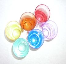
The composition of the proposed glass is optimized in terms of the required properties. Colors affected by the redox state of the glass can be predicted ... |
|
The industrial development is coming with a requirement of new materials. In optic and optoelectronic ... |
|
Research of processes for vitrification of nuclear waste |
||||
 |
Solving the problem of immobilizing a large amount of nuclear waste coming from the production of plutonium is the actual question ... | |||


Experimental techniques
|
|
|

UCT Prague |
IRSM ASCR, v.v.i. |
|
University of Chemistry and Technology Prague Laboratory of Inorganic Materials Technická 5 166 28 Prague 6 Czech Republic
Tel. +420 22044 5192 (l. 4318, 5195) E-mail: Jaroslav.Klouzek@vscht.cz |
Institute of Rock Structure and Mechanics ASCR, v.v.i. Laboratory of Inorganic Materials V Holešovičkách 41 180 00 Prague 8 Czech Republic
Tel. +420 266009 421 (l. 423) |
|
Public transportation: |
Public transportation: Metro Line "C" to Holešovice station, exit to Kobylisy, Prosek, then by bus 102, 210 to Vychovatelna station. Metro Line "B" to Palmovka station, exit to Divadlo pod Palmovkou, then by tram 10, 24, 25 to Vychovatelna station. |
DATA
stdClass Object
(
    [nazev] =>
    [seo_title] => Research
    [seo_desc] =>
    [autor] =>
    [autor_email] =>
    [obsah] =>
Research areas |
Glass melting processes and their modelling |
New glass melting concepts |
|||
|
|
Mathematical modeling is traditional tool for the analysis of glass melting process. CFD methods calculate velocity and temperature fiels ... |
|
New relative value – space utilization – quantitatively assesses melting processes in continuous melting space. The current industrial furnaces... | |
Development of new types of glasses |
Materials for photonics and optoelectronics |
|||
|
|
The composition of the proposed glass is optimized in terms of the required properties. Colors affected by the redox state of the glass can be predicted ... |
|
The industrial development is coming with a requirement of new materials. In optic and optoelectronic ... |
|
Research of processes for vitrification of nuclear waste |
||||
|
Solving the problem of immobilizing a large amount of nuclear waste coming from the production of plutonium is the actual question ... | |||
Experimental techniques
|
|
|
Mathematical simulation of glass melting processes |
||
|
|
Mathematical modeling is traditional tool for the analysis of glass melting processes. CFD methods (Computed Fluid Dynamics) simulation based on the transfer of mass, momentum and energy calculate velocity and temperature of the melt in the melter. Figure shows the calculated temperature fields on the melter top melt surface. |
|
Bubble behaviour in glass melts |
||
|
|
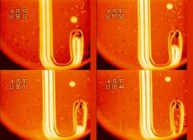
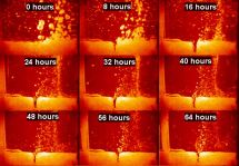
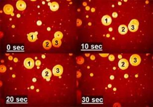
Gaseous or solid inclusions are the most common cause unacceptable product defects and may adversely affect the operation of the device. For a description of their behavior in the melt, we use a combination of experimental and mathematical techniques. The experiments reveal the mechanism of controlling phenomena, provide the input data and verify the mathematical model. Mathematical description, which is based on a set of differential equations describing the rate of change of the bubble size and composition is usually applied to the pre-computed velocity and temperature fields. Figure shows the sequence of visual observation of changes in bubble size, which is used to verify the mathematical description of the interaction of bubbles with the melt. |
|
Nucleation of bubbles |
||
 |
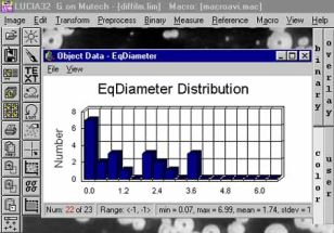
Methods of high-temperature observation and image analysis were used to determine the temperature at which bubbles nucleate at a platinum wire immersed in the glass melt. Bubbles growing during slow linear increase in temperature were identified and their diameter measured. The dependence between the diameter of bubbles and the temperature was extrapolated to zero size of the respective bubbles, and thus determines the temperature of nucleation. |
|
Chemical reactions evolving gases |
||
 |
In particular, reactions of sulfur compounds with reducing or oxidizing agents affect nucleation and separation bubbles, foaming of the melt and dissolution of the refractory particles.
Influencing the reactions kinetics can optimize the melting process. |
|
Corrosion of refractories by melts |
||
 |
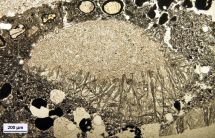
Isothermal static or dynamic corrosion tests follow the mechanism and kinetics of corrosion processes, evaluates changes in the microstructure of the refractories and predict the amount resulting from defects in the glass - blisters and crystalline inclusions. Figure on the left shows an arrangement of the plate corrosion test. Figure on the right illustrates the change in microstructure of refractory materials due to corrosion by an alkali melt - the conversion of mullite grain to secondary tabular corundum. |
|
Electrochemical processes at the interface of electrode and molten glass |
||
|
|
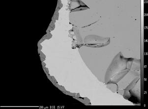
The causes and mechanisms of corrosion, development of bubbles and the release of condensed reaction products at the interface of materials, in particular molybdenum, platinum and tin-oxide based material are studied. The following experimental techniques are used: the electrical potential monitoring, the evaluation of the direct electrode mass losses, the study of the interface electrode-melt by SEM analysis (Figure on the left - SEM image of the excluded Sb under a layer Mo2S3 on the Mo electrode) and visual observation of high-temperature processes in melt (Figure on the right - Development of oxygen bubbles on a Pt electrodes in a borosilicate glass melt under the passage of electrical current). |
|
Identification of bubble sources in industrial melting space |
||
|
|
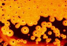
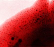
For the expected sources the laboratory measurements of the bubble size distribution, composition and release frequency of bubbles into the melt is performed. The results create a knowledge data base. Experimental values forms also the boundary conditions of the mathematical model of the bubble behavior in the melting furnace. The comparison of product defects analyses and the values obtained from the database and the results of the model makes possible to locate the source of the defects. Figures show examples of experimental tracking the bubble sources – determination of the size distribution and the number of bubbles released from the refractory at the bottom and walls of the melter (left) or from the interface between the batch and the melt (right). |
|
Selected papers |
||
|
||
Research area
As part of an international collaboration, we are working in our laboratory to develop a model for the melting of the glass batch/feed in the melter. Using our mathematical model, we will be able to predict the glass production rate and help to optimize the entire melting process.
Nuclear Waste vitrification
In Hanford, in the northwest of the US in Washington, more than 200,000 m3 of radioactive waste is stored in underground tanks, a result of the plutonium production during the II. World war and Cold war. This waste is stored in 177 aging underground tanks, which have problems with leakage that leads to the contamination of underground and threatens the nearby Columbia River, the second largest river on the Pacific coast of North America.
In order to process and stabilize the radioactive waste, a Waste Treatment Plant (WTP) is now being built at Hanford. The radioactive waste will be mixed with glass-forming and glass-modifying chemicals and melted at 1150 °C in an electric furnace. The resulting glass will be poured into stainless-steel canisters, where the glass will cool and solidify. In the form of glass, the radioactive waste will be stable and safe for a long-term storage in an underground repository.
Although the vitrification of radioactive waste is a proven technology that has been successfully employed for decades, it has never been used on such a large scale and for such complex nuclear waste, as is stored at Hanford. The vitrification plant is thus a huge engineering challenge and one of the world's most complex remediation projects. For example, only the waste pre-treatment and separation plant (dividing the waste into low-activity and high-level fractions) has a ground plan of 165 x 65 meters, and is 12 floors high.
Our group has a long-history working on various aspects of waste glass melting at Hanford. In 2018, another two-year grant from Department of Energy (DoE USA) was awarded to our laboratory to work on the nuclear waste vitrification project at Hanford.
Selected publications
- Lee S., Hrma P., Pokorny R., Klouzek J., VanderVeer B., Rodriguez C., Chun J., Schweiger M., Kruger A. (2017). Effects of alumina sources (gibbsite, boehmite, and corundum) on melting behavior of high-level radioactive waste melter feed. MRS ADVANCES. 2, 11, 603-608.
doi: 10.1557/adv.2016.644 - Lee S., Hrma P., Pokorny R., Klouzek J., VanderVeer B.J., Dixon D.., Luksic S.A., Rodriguez C.P., Chun J., Schweiger M.J., Kruger A.A. (2017). Effect of melter feed foaming on heat flux to the cold cap. Journal of Nuclear Materials. 496, 54-65. doi: 10.1016/j.jnucmat.2017.09.016
- Lee S., Hrma P., Kloužek J., Pokorný R., Hujová M., Dixon D.R., Schweiger M.J., Kruger A.A. (2017): Balance of oxygen throughout the conversion of a high-level waste melter feed to glass. Ceramics International. 43, 13113-13118. doi: 10.1016/j.ceramint.2017.07.002
- Hujova M., Pokorny R., Klouzek J., Dixon D.R., Cutforth A., Seungmin Lee, McCarthy B.P., Michael J. Schweiger M.J., Kruger A.A., Hrma P. (2017): Determination of Heat Conductivity of Waste Glass Feed and its Applicability for Modeling the Batch-to-Glass Conversion. Journal of the American Ceramic Society. 100, 5096-5106. doi: 10.1111/jace.15052
- Lee, S., VanderVeer, B. J., Hrma, P., Hilliard, Z. J., Heilman-Moore, J. S., Bonham, C. C., Pokorny, R., Dixon, D. R., Schweiger, M. J. and Kruger, A. A. (2017). Effects of Heating Rate, Quartz Particle Size, Viscosity, and Form of Glass Additives on High-Level Waste Melter Feed Volume Expansion. Jornal of the American Ceramic Society. doi:10.1111/jace.1462
- Pokorný R., Hilliard Z., Dixon D., Schweiger M., Guillen D., Kruger A., Hrma P. (2015). One-Dimensional Cold Cap Model for Melters with Bubblers. Journal of the American Ceramic Society, 98, 3112-3118.
- Richard Pokorny
- Jaroslav Klouzek
- Miroslava Hujova
- Preparation of glasses under defined conditions
- Visual observation of glass melting processes
- Solubilities of gases in melts
- Diffusion coefficients of gases in melts
- Image analysis
- Evolved gas analysis
- Oxygen partial pressure in melts
Utilization of melting space |
||
|
|
New relative value – space utilization (u) – was introduced. u = v.τH / V (v - volume flow, τH - geometric residence time, and V - the volume of the reactor), The (u) value quantitatively assesses the main melting processes, i.e. the particle dissolution and the bubble removal in a continuous melting space. The (u) value is obtained by mathematical modeling and incorporates the dead volume (unused for processes) of melting space. The current industrial furnaces have a value of less than 0.1 due to disadvantage type of flow. Modeling of various types of flows in model space shows that the value up to 0.8 can be reached by establishing a certain type spiral flow (proportional to increase performance and reduce heat losses). Favorable modeling results are transmitted to the real melting facilities and also serve on the draft designs of new melting spaces. |
|
Behaviour of bubbles in centrifugal field |
||
 |
The competition of two phenomena takes place in the centrifugal field: bubble dissolution and centrifugation. Skimming is a faster process on favorable terms. Mathematical and experimental modeling can find optimal process conditions. Optimum conditions can be applied to melt glass or other viscous liquids, provided similar behavior of bubbles. The figure shows the dependence between time of the bubble removal and rotational velocity. | |
Behaviour of bubbles under reduced pressure |
||
 |
Experimental modeling in laboratory conditions showed that the reduction of the external pressure in the range of 20 - 40 kPa at temperatures around 1300°C brings roughly the same intensity of the bubble removal process as in conventional melting furnaces working under normal pressure and at maximal temperatures in the melt above 1500°C. Moreover, it is often possible to significantly reduce the concentration of environmentally problematic refining agents. The figure on the left presents the results of a parametric study showing the dependence of the space pull rate on temperature and pressure. |
|
Selected papers |
||
|
||
Patents |
||
|
||

Development of new types of crystal and coloured glasses |
||
|
|
Research is focused on eliminating oxides of toxic elements, notably lead and barium from the glass. The composition of the proposed glass is optimized in terms of the required technological and utiliyation properties. Colors affected by the redox state of the glass can be predicted by laboratory experiments, especially electrochemical measurements in glass melts. In addition, the laboratory experiments and proposed models follow the color formation by other mechanisms, such as crystalization of in the glass melts (Au, Ag and Cu ruby). The figure shows a TEM image of gold nano crystals in a gold ruby glass. |
|
Patents |
||
|
||
Materials for photonics and optoelectronics |
|
|
|
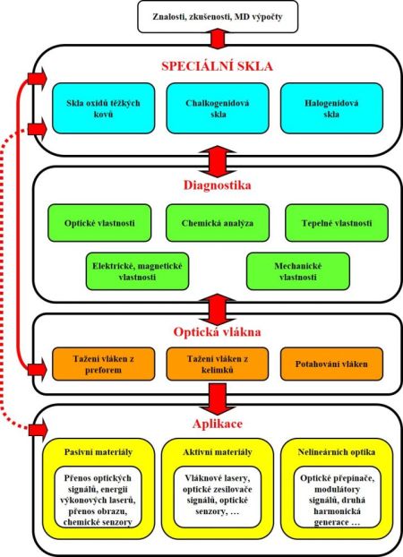
The industrial development is coming with other and other requests for a new materials. The way is same in optic and optoelectronic (interdisciplinary flied dealing with transfer and processing of optic signal) fields and in other related ones. The special glasses can be divided in following base group, as the schema of single description of researching problems shows: Halide glasses often toxic, volatilize by preparation, sensitive to humidity, radiation transmit in UV/VIS-MIR areas Chalcogenide glasses preparation must be done at inert atmosphere or vacuum (other way its react with an air), often content with toxic compound (As), radiation transmit in VIS/NIR-MIR areas Heavy metal oxide (HMO) glasses problems with the purity products, big disadvantage is containing OH- groups inductive of huge absorption at wave length 2.9 mm; radiation transmit in VIS-NIR/MIR areasMixed glassesfor example halide-oxygen, chalcigenide-halide, … |
|
Application of special glasses: |
|
Selected papers |
||
|
Experimental techniques
|
|
|
|
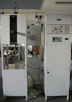
Laboratorní pec s hermetickým topným prostorem umožňuje tavení vzorků v definované atmosféře v rozmezí tlaků 1-150 kPa při maximální teplotě 1400°C. Po vložení vzorku se probíhá několikanásobné opakované odčerpání a naplnění topného prostoru požadovaným plynem nebo směsí plynů. Během ohřevu plyn proudí topným prostorem. Při tavení v redukční atmosféře (vodík nebo jeho směs s dusíkem) se plyn na výstupu z prostoru spaluje vestavěným hořákem. |
|
|
|
|
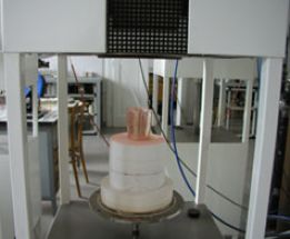
Pneumatický posuv vzorků do topného prostoru. |
|
|
|
|
|
Laboratorní pec s řídící jednotkou. |
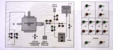
Schéma rozvodu plynů pro řízení atmosféry v topném prostoru |
|
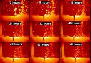
Metoda využívá průhlednosti většiny skel ve viditelné oblasti (případně v blízké infračervené kolem 2 mm) i za tavicích teplot. Principem metody je sledování vzorku nacházejícího se v křemenné kyvetě a v laboratorní peci s průhledem. Průběh děje je sledován digitální videokamerou. Obrazový záznam se vyhodnocuje analyzátorem obrazu Lucia.Při sledování taveniny s bublinami se snímá buď přímo obraz vzniklý po roztavení vsázky, nebo se v již utavené a vyčeřené sklovině připravují vyfouknutím umělé bubliny, které se pak dále sledují. Metoda je využívána k vysokoteplotnímu pozorování tavicího procesu, čeřicích procesů, tvorbě pěny v tavenině, pozorováním hladiny lze získat informaci o chování pěny nebo o stabilitě bublin na hladině. Tato metoda se též používá ke stanovení teploty nukleace bublin. Teplota sekundární tvorby bublin (reboilu) je stanovována na základě přímého vizuálního sledování vzniku bublin na platinovém drátku ponořeného do skla. Teplota vzorku je zvyšována rychlostí 2°C/min. Pozorovaný růst vytvořené bubliny s teplotou je vyhodnocen analyzátorem obrazu a teplota reboilu je stanovena extrapolací na nulový rozměr bubliny. Další použití metody je sledování vývoje bublin ze žárovzdorných materiálů - korozní testy žárovzdorných materiálů. |
|
|
|
Schéma experimentální metody |
 |
 |
|
Uvolňování bublin ze žáromateriálu |
Vyhodnocení měření pomocí obrazové analýzy |
|
|
|
Sledování růstu a rozpouštění bublin |
| Stanovení rozpustností plynů v taveninách se skládá ze dvou kroků. V prvním kroku probíhá sycení taveniny čistým plynem. Po dosažení rovnováhy se tavenina rychle ochladí na pokojovou teplotu. Koncentrace rozpuštěného plynu je pak stanovena plynově chromatografickou metodou popsanou dále. Principem metody stanovení plynů rozpuštěných v tavenině skla je kontinuální extrakce vzorku proudem inertního plynu a následná chromatografická analýza uvolněných plynů. Analyzovaný vzorek skla ve formě trámečku s rozměry 5 x 5 x 10 mm je umístěn ve zkumavce z křemenného skla zasunuté v laboratorní trubkové peci vyhřáté na teplotu 1500 °C. U dna zkumavky ústí kapilára z křemenného skla, kterou proudí helium. Uvolněné plyny se zachycují v koncentrovací smyčce ponořené v kapalném dusíku. Po ukončení extrakce (60 minut) se smyčka rychle zahřeje ponořením do horkého oleje a přepojí do okruhu nosného plynu chromatografu. Metoda stanovení umožňuje současné stanovení oxidu uhličitého, kyslíku, dusíku a oxidu sírového. Ostatní ve skle rozpuštěné plyny, tzn. vodní páru, a případně argon, nelze v uvedeném uspořádání stanovit. | |
 |
|
|
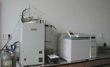
Měřící aparatura pro analýzu plynů v taveninách |
Schéma sycení taveniny plynem |
|
Schéma aparatury pro stanovení plynů v taveninách
|
 |
|
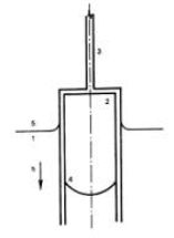
Princip metody je zřejmý z obrázku 1. Plyn, jehož difúzní koeficient se měří se zavede platinovou trubičkou do válcovité nádobky z křemenného skla, která se nachází těsně nad hladinou roztaveného skla uvnitř optické kyvety umístěné v laboratorní peci. Nádobka se po naplnění plynem zasune pod hladinu taveniny. Absorpce plynu se indikuje vzestupem taveniny uvnitř nádobky, který je snímán videokamerou speciálním otvorem v boku laboratorní pece, viz obr. 2. K vyhodnocení měření se používá analyzátor obrazu, měřící vzdálenost rozhraní plyn-tavenina od horního konce nádobky.
|
|
|
Schéma experimentálního uspořádání metody 1 - kyveta s taveninou skla 2 - válcovitá měřící nádobka z křemenného skla 3 - držák měřící nádobky 4 - pohybující se rozhraní plyn-tavenina 5 - hladina taveniny uvnitř kyvety |
|
|
|
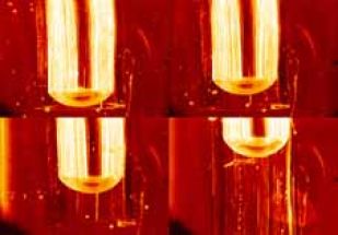
Pohyb rozhraní plyn-tavenina při měření difúzního koeficientu vodní páry sodno-vápenato-křemičité sklovině, teplota 1200 °C. a) 15000 s, b) 20000 s, c) 40000 s, d) 60000 s |
|
Používáme systém LUCIA (Laboratory Universal Computing Image Analysis) vyvinutý firmou Laboratory Imaging. Analyzátor obrazu tvoří standardní osobní počítač se zabudovanou obrazovou kartou umožňující přímo snímat obrazový signál z videokamery nebo z videorekordéru. Při zpracování obrazu z mikroskopu nebo z vysokoteplotního sledování dějů v taveninách využíváme obvykle funkce měření délky a počtu a rozdělení velikosti částic.
|
|
|
|
Měření posunu rozhraní plyn-tavenina uvnitř nádobky z křemenného skla při stanovení difúzního koeficientu plynu v tavenině. |
|
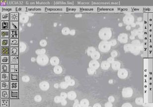
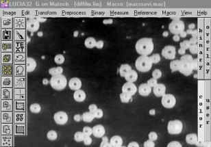
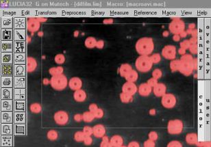
Měření počtu a rozdělení velkostí bublin uvolňovaných ze žáromateriálu do taveniny: |
|
Původní obrázek
|
|
|
|
Úprava kontrastu
|
|
|
|
Měření pole uvnitř měřícího rámečku
|
|
|
|
Výsledek měření |
|
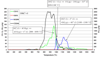
Měřící aparatura je stejná jako v případě analýzy plynů rozpuštěných v taveninách. Analyzovaný vzorek vstupní směsi sklářských surovin je umístěn ve zkumavce z křemenného skla zasunuté v laboratorní trubkové peci. U dna zkumavky ústí kapilára z křemenného skla, kterou proudí helium. Teplota v peci se zvyšuje definovanou lineární rychlostí. Helium unáší uvolněné plyny do dávkovacích smyček plynového chromatografu. Výsledkem analýzy je teplotní závislost množství uvolněných plynů. |
|
|
|
|
|
Měřicí aparatura |
Analýza uvolněných plynů vsázky Na2O-CaO-SiO2 skla s přídavkem C a Na2SO4 |
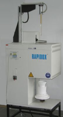
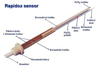
Při posuzování podmínek vzniku vad ve sklovině hraje velmi důležitou roli i tzv. redox stavu skloviny. Redox stav vyjadřuje vztah mezi vyššími a nižšími oxidačními formami iontů přechodných kovů, přítomných ve sklovině. Jedná se především o ionty železa, chrómu, barvících oxidů a dále čeřících přísad. Měření redox stavu umožňuje kontrolu výsledné barvy skloviny, jejího ohřívání i ochlazování (hodnota efektivní tepelné vodivosti) a průběhu odstraňování bublin (čeřící proces). Hodnota redox stavu skloviny je rovněž významným údajem při výpočtech rozložení oxidačně-redukčních složek ve sklářských tavících prostorech, při výpočtu chování bublin, významných pro optimalizaci čeřícího procesu a pro identifikaci zdrojů bublin. Komerčně dostupnou metodou měření redox stavu skloviny je systém Rapidoxâ Principem stanovení je elektrochemické měření rovnovážného napětí mezi referenční a měřící elektrodou. Měřící elektrodu tvoří Pt nebo Ir drát. Referenční elektroda je umístěna ve směsi Ni/NiO zaručující definovaný parciální tlak kyslíku. Vodivé spojení mezi měřenou taveninou a refereční směsí tvoří přepážka z oxidu zirkoničitého v kubické modifikaci. Z naměřené hodnoty elektromotorického napětí E (V) se za pomoci Nernstovy rovnice vypočte parciální tlak kyslíku:
![]()
kde: F - Faradayova konstanta (96 500 C) R - plynová konstanta (8,314 J mol-1K-1) T - absolutní teplota Tabulka 2 uvádí hodnoty parciálního tlaku kyslíku ve vybraných typech sklovin při teplotě 1200 °C.
Parciální tlak kyslíku v některých typech průmyslových sklovin při teplotě 1200 °C.
| Sklovina | pO2 (Pa) |
| float | 8000 |
| bílá obalová | 10000 |
| barnatý křišťál | 1000 |
| zelená obalová | 350 |
| amber | 5 x 10⁻⁴ |
|
|
|
|
Měřící systém Rapidox |
Měřící sonda |
|
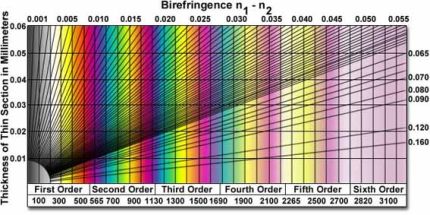
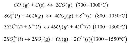
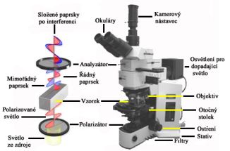
Polarizační mikroskopie si přes svou více jak 170ti letou tradici stále udržuje platné místo v oboru studia materiálů. Metoda využívá interakce polarizovaného světla s opticky anisotropními látkami, při které dochází k tzv. dvojlomu. Původní paprsek se po průchodu vzorkem rozdělí na dva nové, řádný a mimořádný, které jsou navzájem fázově posunuté (šíří se různou rychlostí) a kmitají v různých rovinách. V analyzátoru mikroskopu se oba paprsky složí do stejné roviny kmitu a jejich fázový posun se projeví vznikem interferenčních barev. Polarizační mikroskopii lze proto charakterizovat jako metodu zvýšení kontrastu mikroskopického obrazu. Použití však nachází i dnes jako doplňková metoda identifikace krystalických látek, např. měřením výše dvojlomu s použitím Berekova kompenzátoru.
|
|
|
|
Polarizační mikroskop Olympus BX 51P |
|
|
|
Michel-Lévyho stupnice interferenčních barev pro určování výše dvojlomu |